Netlisting
Using gnetlist
Given a well-formed gschem circuit specification file we can use the gnetlist tool
that comes with the gEDA suite to export it to a QHDL-file.
Using the command-line, if the .sch schematic file is located at the path my_dir/my_schematic.sch,
and you wish to produce a QHDL file at the location my_other_dir/my_netlist.qhdl, run the following command:
gnetlist -g qhdl my_dir/my_schematic.sch -o my_other_dir/my_netlist.qhdl
It is generally a very good idea to inspect the produced QHDL file code and verify that it looks like it
should before trying to compile it into a python circuit_component library file.
The QHDL Syntax
A QHDL file consists of two basic parts:
An
entitydeclaration, which should be thought of as defining the external interface of the specified circuit. I.e., it defines global input and output ports as well as parameters for the overall model.A corresponding
architecturedeclaration, that, in turn consists of two parts:
The architecture head defines what types of components can appear in the circuit. I.e., for each
componentdeclaration in the architecture head, there can exist multiple instances of that component type in the circuit. The head also defines the internalsignallines of the circuit.The architecture body declares what instances of which component type exists in the circuit, how its ports are mapped to the internal signals or entity ports, and how its internal parameters relate to the entity parameters. In QHDL, each signal may only connect exactly two ports, where one of three cases is true:
- It connects an entity input with a component instance input
- It connects an entity output with a component instance output
- It connects a component output with a component input
Before showing some examples of QHDL files, we present the general QHDL syntax in somewhat abstract form.
Here, square brackets [optional] denote optional keywords/syntax and the ellipses ... denote repetition:
-- this is a comment

-- entity definition
-- this serves as the external interface to the circuit, specifying inputs and outputs
-- as well as parameters of the model
entity my_entity is
    [generic ( var1: generic_type [:= default_var1]] [; var2: generic_type [...] ...]);]
    port (i_1,i_2,...i_n:in fieldmode; o_1,o_2,...o_n:out fieldmode);
end entity my_entity;

-- architecture definition
-- this is the actual implementation of the entity in terms of subcomponents
architecture my_architecture of my_entity is
    -- architecture head
    -- each type of subcomponent, i.e. its ports and its parameters are defined here similarly
    -- to the entity definition above
    component my_component
        [generic ( var3: generic_type [:= default_var3]] [; var4: generic_type [...] ...]);]
        port (p1,p2,...pm:in fieldmode; q1,q2,...qm:out fieldmode);
    end component my_component;

    [component my_second_component
        [generic ( var5: generic_type [:= default_var5]] [; var6: generic_type [...] ...]);]
        port (p1,p2,...pr:in fieldmode; q1,q2,...qr:out fieldmode);

    end component my_second_component;

    ...

    ]

    -- internal signals to connect component instances
    [signal s_1,s_2,s_3,...s_m fieldmode;]


begin
    -- architecture body
    -- here the actual component instances are defined and their ports are mapped to signals
    -- or to global (i.e. entity-) ports
    -- furthermore, global (entity-) parameters are mapped to component instance parameters.

    COMPONENT_INSTANCE_ID1: my_component
        [generic map(var1 => var3, var1 => var4);]
        port map (i_1, i_2, ... i_m, s_1, s_2, ...s_m);

    [COMPONENT_INSTANCE_ID2: my_component
        [generic map(var1 => var3, var1 => var4);]
        port map (s_1, s_2, ... s_m, o_1, o_2, ...o_m);

    COMPONENT_INSTANCE_ID3: my_second_component
        [generic map (...);]
        port map (...);
    ...
        ]

 end architecture my_architecture;
where generic_type is one of int, real, or complex.
QHDL-Example files:
A Mach-Zehnder-circuit
This toy-circuit realizes a Mach-Zehnder interferometer.
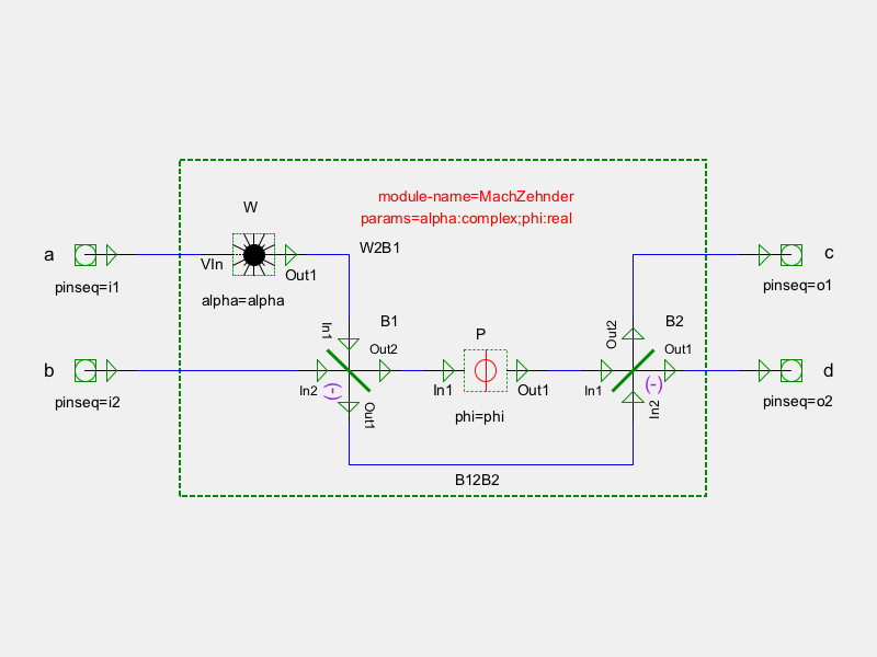
-- Structural QHDL generated by gnetlist
-- Entity declaration

ENTITY MachZehnder IS
    GENERIC (
        alpha : complex;
        phi : real);
    PORT (
        a : in fieldmode;
        b : in fieldmode;
        c : out fieldmode;
        d : out fieldmode);
END MachZehnder;


-- Secondary unit
ARCHITECTURE netlist OF MachZehnder IS
    COMPONENT Phase
    GENERIC (
        phi : real);
    PORT (
        In1 : in fieldmode;
        Out1 : out fieldmode);
    END COMPONENT ;

    COMPONENT Beamsplitter
    GENERIC (
        theta : real := 0.7853981633974483);
    PORT (
        In1 : in fieldmode;
        In2 : in fieldmode;
        Out1 : out fieldmode;
        Out2 : out fieldmode);
    END COMPONENT ;

    COMPONENT Displace
    GENERIC (
        alpha : complex);
    PORT (
        VIn : in fieldmode;
        Out1 : out fieldmode);
    END COMPONENT ;

    SIGNAL B12B2 : fieldmode;
    SIGNAL W2B1 : fieldmode;
    SIGNAL P2B2 : fieldmode;
    SIGNAL B12P : fieldmode;
    SIGNAL unnamed_net4 : fieldmode;
    SIGNAL unnamed_net3 : fieldmode;
    SIGNAL unnamed_net2 : fieldmode;
    SIGNAL unnamed_net1 : fieldmode;
BEGIN
-- Architecture statement part
    W : Displace
    GENERIC MAP (
        alpha => alpha);
    PORT MAP (
        VIn => unnamed_net1,
        Out1 => W2B1);

    B2 : Beamsplitter
    PORT MAP (
        In1 => P2B2,
        In2 => B12B2,
        Out1 => unnamed_net4,
        Out2 => unnamed_net3);

    B1 : Beamsplitter
    PORT MAP (
        In1 => W2B1,
        In2 => unnamed_net2,
        Out1 => B12B2,
        Out2 => B12P);

    P : Phase
    GENERIC MAP (
        phi => phi);
    PORT MAP (
        In1 => B12P,
        Out1 => P2B2);

-- Signal assignment part
unnamed_net2 <= b;
unnamed_net1 <= a;
d <= unnamed_net4;
c <= unnamed_net3;
END netlist;
A Pseudo-NAND-gate
This circuit consists of a Kerr-nonlinear cavity, a few beamsplitters and a bias input amplitude to realize a NAND-gate for the inputs A and B. For details see [Mabuchi11].
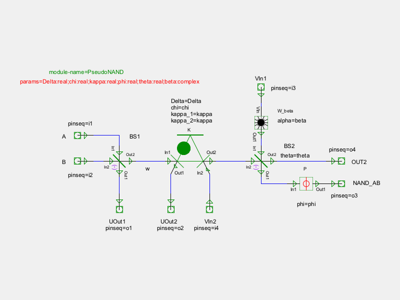
The gschem schematic from which the QHDL file below was automatically created.
-- Structural QHDL generated by gnetlist
-- Entity declaration

ENTITY PseudoNAND IS
    GENERIC (
        Delta : real;
        chi : real;
        kappa : real;
        phi : real;
        theta : real;
        beta : complex);
    PORT (
        A : in fieldmode;
        B : in fieldmode;
        VIn1 : in fieldmode;
        VIn2 : in fieldmode;
        UOut1 : out fieldmode;
        UOut2 : out fieldmode;
        NAND_AB : out fieldmode;
        OUT2 : out fieldmode);
END PseudoNAND;


-- Secondary unit
ARCHITECTURE netlist OF PseudoNAND IS
    COMPONENT KerrCavity
    GENERIC (
        Delta : real;
        chi : real;
        kappa_1 : real;
        kappa_2 : real);
    PORT (
        In1 : in fieldmode;
        In2 : in fieldmode;
        Out1 : out fieldmode;
        Out2 : out fieldmode);
    END COMPONENT ;

    COMPONENT Phase
    GENERIC (
        phi : real);
    PORT (
        In1 : in fieldmode;
        Out1 : out fieldmode);
    END COMPONENT ;

    COMPONENT Beamsplitter
    GENERIC (
        theta : real := 0.7853981633974483);
    PORT (
        In1 : in fieldmode;
        In2 : in fieldmode;
        Out1 : out fieldmode;
        Out2 : out fieldmode);
    END COMPONENT ;

    COMPONENT Displace
    GENERIC (
        alpha : complex);
    PORT (
        VacIn : in fieldmode;
        Out1 : out fieldmode);
    END COMPONENT ;

    SIGNAL unnamed_net11 : fieldmode;
    SIGNAL unnamed_net10 : fieldmode;
    SIGNAL unnamed_net9 : fieldmode;
    SIGNAL unnamed_net8 : fieldmode;
    SIGNAL unnamed_net7 : fieldmode;
    SIGNAL unnamed_net6 : fieldmode;
    SIGNAL unnamed_net5 : fieldmode;
    SIGNAL unnamed_net4 : fieldmode;
    SIGNAL unnamed_net3 : fieldmode;
    SIGNAL unnamed_net2 : fieldmode;
    SIGNAL unnamed_net1 : fieldmode;
    SIGNAL w : fieldmode;
BEGIN
-- Architecture statement part
    W_beta : Displace
    GENERIC MAP (
        alpha => beta);
    PORT MAP (
        VacIn => unnamed_net6,
        Out1 => unnamed_net11);

    BS2 : Beamsplitter
    GENERIC MAP (
        theta => theta);
    PORT MAP (
        In1 => unnamed_net11,
        In2 => unnamed_net3,
        Out1 => unnamed_net10,
        Out2 => unnamed_net8);

    BS1 : Beamsplitter
    PORT MAP (
        In1 => unnamed_net4,
        In2 => unnamed_net5,
        Out1 => unnamed_net7,
        Out2 => w);

    P : Phase
    GENERIC MAP (
        phi => phi);
    PORT MAP (
        In1 => unnamed_net10,
        Out1 => unnamed_net9);

    K : KerrCavity
    GENERIC MAP (
        Delta => Delta,
        chi => chi,
        kappa_1 => kappa,
        kappa_2 => kappa);
    PORT MAP (
        In1 => w,
        Out1 => unnamed_net1,
        In2 => unnamed_net2,
        Out2 => unnamed_net3);

-- Signal assignment part
unnamed_net6 <= VIn1;
unnamed_net2 <= VIn2;
unnamed_net5 <= B;
unnamed_net4 <= A;
NAND_AB <= unnamed_net9;
OUT2 <= unnamed_net8;
UOut2 <= unnamed_net1;
UOut1 <= unnamed_net7;
END netlist;
A Pseudo-NAND-Latch
This circuit consists of two subcomponents that each act almost (i.e., for all relevant input conditions) like a NAND logic gate in a symmetric feedback conditions. As is known from electrical circuits this arrangement allows the fabrication of a bi-stable system with memory or state from two systems that have a one-to-one input output behavior. See also [Mabuchi11]
--pseudo-NAND latch with explicit parameter dependence
entity PseudoNANDLatch is
    generic (Delta, chi, kappa, phi, theta : real;
             beta : complex);

    port (NS, W1, kerr2_extra, NR, W2, kerr1_extra : in fieldmode;
          BS1_1_out, kerr1_out2, OUT2_2, BS1_2_out, kerr2_out2, OUT2_1 : out fieldmode);
end PseudoNANDLatch;

architecture latch_netlist of PseudoNANDLatch is
    component PseudoNAND
        generic (Delta, chi, kappa, phi, theta : real;
                 beta : complex);
        port (A, B, W_in, kerr_in2 : in fieldmode;
              uo1, kerr_out1, NAND_AB, OUT2 : out fieldmode);
    end component;

    signal FB12, FB21 : fieldmode;      -- feedback signals

begin
    NAND2 : PseudoNAND
    generic map (
        Delta => Delta, chi => chi, kappa => kappa, phi => phi, theta => theta, beta => beta);
    port map (
        A => NR, B => FB12, W_in => W2, kerr_in2 => kerr2_extra,
        uo1 => BS1_2_out, kerr_out1 => kerr2_out2, NAND_AB => FB21, OUT2 => OUT2_2);

    NAND1 : PseudoNAND
    generic map (
        Delta => Delta, chi => chi, kappa => kappa, phi => phi, theta => theta, beta => beta);
    port map (
        A => NS, B => FB21, W_in => W1, kerr_in2 => kerr1_extra,
        uo1 => BS1_1_out, kerr_out1 => kerr1_out2, NAND_AB => FB12, OUT2 => OUT2_1);
end latch_netlist;